Predicting Transient Macro Gap Thermal Conductance Decoupling on Micro Structured Cavity Insets
Predicting transient macro gap thermal decoupling requires coupling cavity pressure decay kinetics with non-linear contact mechanics to model thermal resistance spikes.

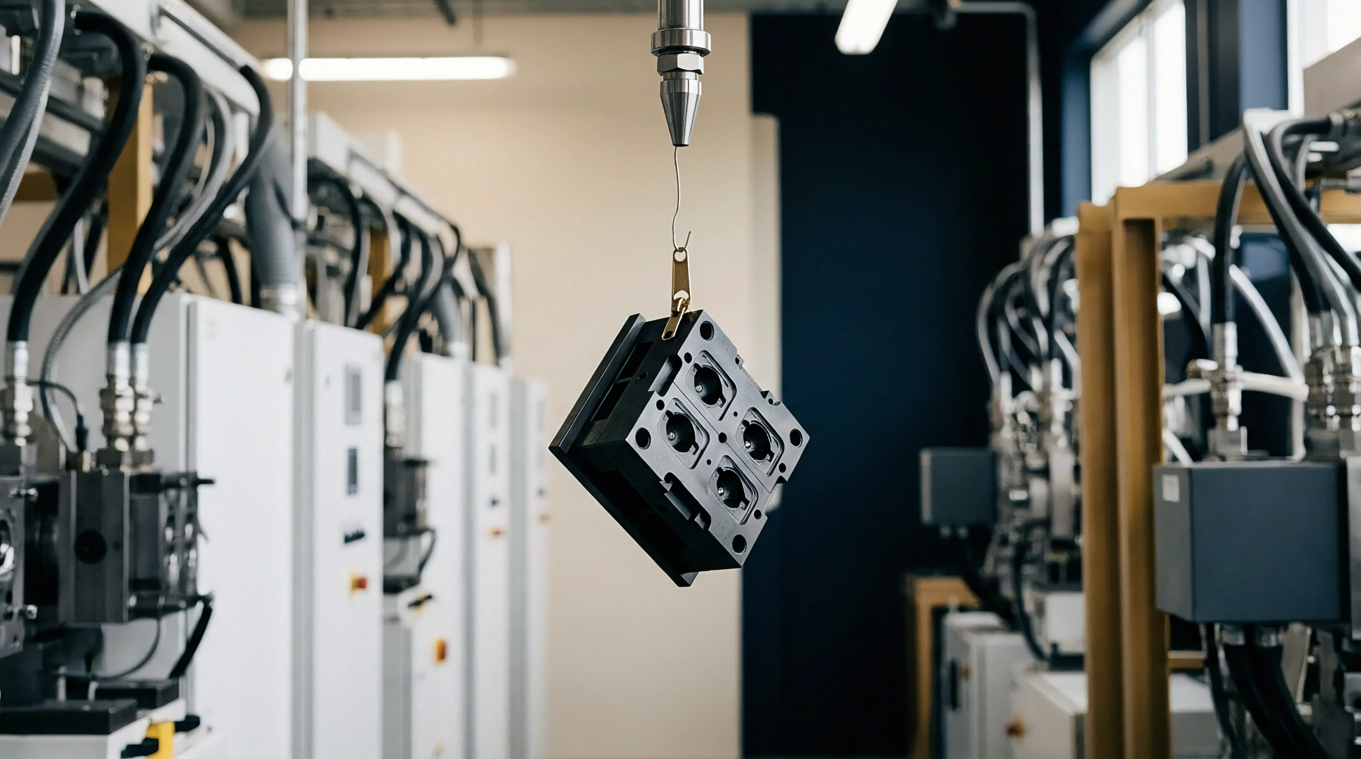
Precision tooling for micro-structured components relies on discrete tool inserts fitted within a primary mold base. Ground steel housings surround these modular inserts to isolate expensive micro-machining or electroforming processes from the larger core and cavity plates. Machining tolerances under ISO 2768-mK dictate that the receiving recess maintains surface flatness within two micrometers across the seating plane.
When the insert rests against the bottom ground surface, micro-asperities on both metallic faces touch across only a fraction of the nominal contact area. Uncompressed surface roughness values of Rz 1.6 create microscopic voids between the insert base and the recess floor.

Interfacial Seating Mechanics
Direct mechanical contact between metal faces handles the primary heat extraction path during injection molding cycles. Pre-load bolts tightened to specified torque values pull the insert base down against the parent tool steel. Without sufficient pre-load force, initial surface contact remains limited to thirty percent of the geometric surface area.
Fasteners applied at standard assembly torque generate compressive stress levels around fifteen megapascals across the interface. Ground pads positioned beneath the insert distribute this mounting load to prevent tilt during tool assembly.
Dynamic contact conductance drops from 4200 W/m²K to 280 W/m²K when interfacial pressure falls below 2.5 MPa under a 180°C cavity wall condition.
Structural Deflection under Injection Tonnage
High-pressure polymer melt entering the cavity delivers hydraulic force directly onto the micro-structured insert face. Clamping force applied by the molding machine transfers through the core and cavity plates, compressing the entire assembly. Peak cavity pressures reaching one hundred megapascals flex the tool steel surrounding the insert recess.
Elastic deformation alters the physical alignment between the insert sidewalls and the surrounding housing plate. Hydraulic loading momentarily increases interfacial contact pressure across the bottom floor, flattening micro-asperities and maximizing heat flow pathways.
Improper seating torque or uneven floor ground surfaces cause uneven thermal extraction across micro-structured surfaces, leading to localized warpage, non-uniform shrinkage, and early tool fatigue failures.

Contraction
Thermal gradients established during polymer injection drive physical movements between adjacent metal components. Tool steel grades such as 1.2343 exhibit thermal expansion coefficients of 11.8 micrometers per meter Kelvin, whereas copper-beryllium inserts expand at 17.5 micrometers per meter Kelvin. Differential temperature changes during dynamic thermal cycling cause the insert and its surrounding pocket to expand and shrink at unequal rates.
During the heating phase of Variotherm processing, the insert expands faster than the parent cavity plate, closing lateral clearances. As cooling fluid flows through internal channels, rapid temperature drops reverse this expansion differential.

Volumetric Shrinkage and Pressure Decay Kinetics
Molten polymer packed into micro-cavities exerts peak pressure during the holding phase. Polymer molecules cool and crystallize, causing volumetric shrinkage inside the cavity impression. As the internal melt pressure decays from eighty megapascals down to ambient atmospheric levels, the hydraulic force pressing the insert against its seating floor diminishes.
The tool steel relaxes elastically from its peak deflection state. Micro-asperities that were flattened under peak tonnage spring back, reducing the real metal-to-metal contact area.
Formation Thresholds for Interfacial Air Layers
Relief of hydraulic pressure allows microscopic separation to occur at the metal-to-metal interface. A physical gap opens between the insert base and the floor recess. Gap widths ranging from one micrometer to twenty-five micrometers develop within milliseconds of cavity pressure collapse.
Trapped gas within the interface exhibits a thermal conductivity of approximately 0.028 Watts per meter Kelvin, which is orders of magnitude lower than the 29 Watts per meter Kelvin rating of tool steel.
| Clamping Force (kN) | Cavity Pressure (MPa) | Inset Material | Macro Gap Width (µm) | Thermal Conductance (W/m²K) |
|---|---|---|---|---|
| 500 | 85.0 | 1.2343 Tool Steel | 0.4 | 4150 |
| 500 | 40.0 | 1.2343 Tool Steel | 3.2 | 1200 |
| 500 | 5.0 | 1.2343 Tool Steel | 14.8 | 310 |
| 1200 | 85.0 | Ampcoloy 940 | 0.1 | 5800 |
| 1200 | 40.0 | Ampcoloy 940 | 1.8 | 2100 |
| 1200 | 5.0 | Ampcoloy 940 | 8.5 | 490 |
Loss of intimate metal contact during cooling disrupts the predicted heat transfer pathway. Molders frequently observe unexpected cycle extensions and attribute the delayed part cooling to degraded cooling fluid channels or incorrect chiller settings.
- Interfacial Micro Gap Opening occurs when cavity pressure drops below the elastic spring-back threshold of the pocket sidewalls, creating an insulating air pocket.
- Asperity Contact Collapse happens as external hydraulic tonnage falls, reducing the physical contact points between the insert base and pocket floor to less than five percent.
- Transient Conductance Decoupling develops during the late cooling phase, causing thermal contact conductance to fall by up to ninety-five percent before part ejection.
- Thermal Expansion Mismatch Separation arises when high-conductivity copper inserts cool faster than the surrounding steel core plate, pulling away from side positioning datum points.

Transient
Time-dependent thermal phenomena govern the solidification rate of thin-wall micro-molded features. During the first fifty milliseconds of melt injection, high interface conductance ensures rapid heat flow into the insert steel. Micro-features fill completely because mold wall temperatures remain elevated under dynamic heating algorithms.
Once the packing phase completes and the macro gap opens at the insert base, heat removal through the primary tool base slows dramatically. The thermal wave reflecting off the insulated gap boundary causes localized re-heating of the insert face.
Why Does Cavity Pressure Decay Trigger Thermal Decoupling?
Decoupling occurs because mechanical contact pressure at the internal insert boundary directly tracks the internal melt pressure profile. High melt pressure forces the insert tightly against its pocket floor, creating maximum metallic contact. When the gate freezes and polymer shrinkage relieves cavity pressure, the restoring force holding the insert against its base vanishes.
Elastic rebound of the mold base plate pulls the seating surfaces apart by several micrometers, preventing heat from jumping the resulting air gap efficiently.
- Install surface-mounted piezoelectric pressure transducers and fast-response infrared thermocouples directly behind the micro-structured cavity insert.
- Record the baseline thermal decay profile during initial dry cycling using standard oil heating units without polymer injection.
- Inject test shots of semi-crystalline resin while logging simultaneous cavity pressure decay and insert temperature spikes.
- Map the exact millisecond time stamp where insert temperature departure deviates from single-phase Fourier conduction predictions.
- Calculate the instantaneous thermal contact conductance curve by inverse heat conduction modeling across the separation event window.
Heat Transfer Suppression at the Polymer Interface
Reduced heat extraction rates alter the polymer solidification morphology. Polypropylene and polyether ether ketone resins exhibit strong crystallinity changes when cooling rates drop from one hundred Kelvin per second down to ten Kelvin per second. Micro-structured ribs and optical prisms retain heat longer than anticipated.
Delayed heat removal leads to optical birefringence defects, severe sink marks on structural rib intersections, and incomplete replication of sub-micron surface textures.
Interfacial air gaps act as dynamic thermal switches that shift mold cooling mechanisms from metallic conduction to gas phase thermal impedance during the cycle.
In thermal control design, an unanchored insert resting in a dry pocket acts as a variable thermal resistance valve rather than a solid heat conductor.
Impedance
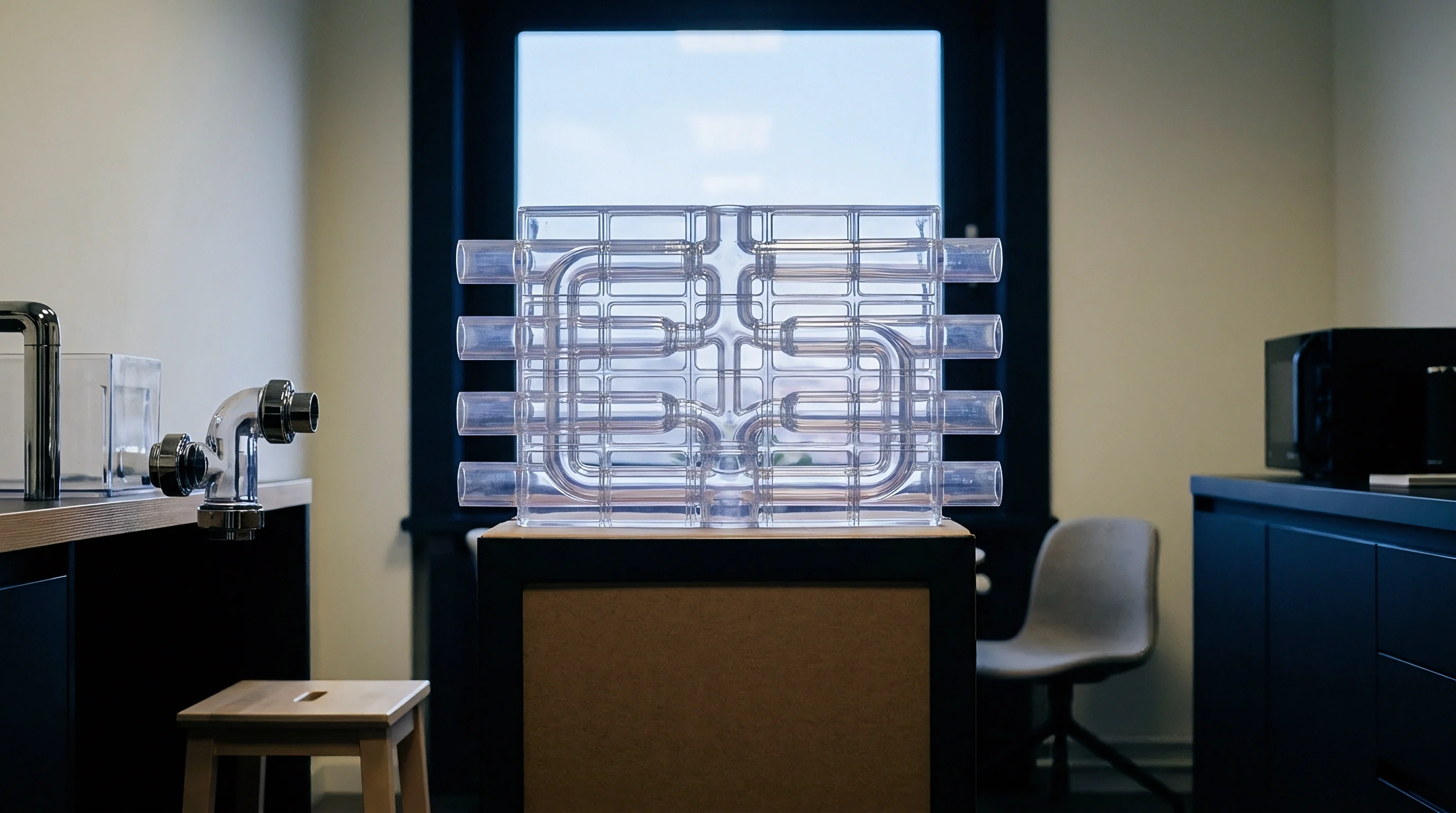
Resistance to thermal transport across solid boundaries depends on micro-scale surface topography and gas transport dynamics. Total thermal contact impedance across the insert interface equals the sum of micro-asperity constriction resistance and micro-gap fluid conduction resistance. When surfaces separate, conduction through the gas medium dominates the heat flux balance.
Knudsen numbers calculated for micrometric gaps indicate that gas molecules undergo infrequent intermolecular collisions within micro-gaps, reducing effective air thermal conductivity below standard atmospheric handbook values.
Mathematical Framing of Interfacial Contact Resistance
Thermal contact conductance h_c across the pocket floor interface follows a non-linear pressure relationship governed by material hardness, surface slope, and contact pressure. The mathematical expression models this conductance variation across changing load regimes:
h_c = 1.25 k_m (m / sigma) (P / H)^0.95 + (k_g / Y)
In this relationship, k_m represents the harmonic mean thermal conductivity of the two touching metals. The parameter m denotes the mean absolute profile slope, while sigma represents the root-mean-square surface roughness. Applied mechanical pressure P acts against the micro-hardness H of the softer substrate metal.
Gas conductivity k_g divided by the separation distance Y models the parallel thermal conduction path through the fluid layer. As pressure P approaches zero during polymer cooling, the metallic constriction term collapses, leaving gas conduction through gap width Y as the sole heat transfer mechanism.
| Polymer Resin Grade | Inset Alloy Substrate | Peak Conductance (W/m²K) | Decoupled Conductance (W/m²K) | Transition Pressure (MPa) |
|---|---|---|---|---|
| Polycarbonate (PC) | 1.2343 Steel | 3800 | 210 | 12.5 |
| Polycarbonate (PC) | Ampcoloy 940 | 5200 | 340 | 11.0 |
| Polyphenylene Sulfide (PPS) | 1.2343 Steel | 4100 | 190 | 18.0 |
| Liquid Crystal Polymer (LCP) | Titanium Grade 5 | 2200 | 120 | 22.5 |
| Polypropylene (PP) | Aluminum 7075 | 4600 | 310 | 8.0 |

Experimental Measurement via Embedded Thermocouple Arrays
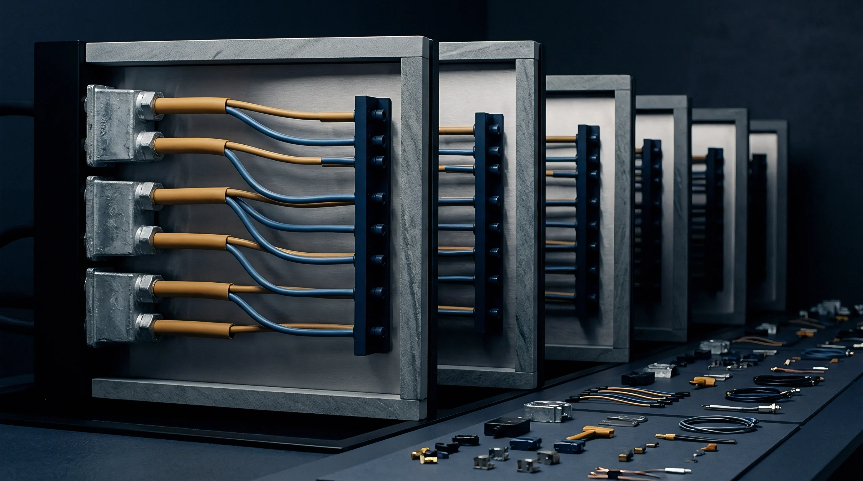
Quantifying transient macro gap decoupling requires high-speed sensory arrays embedded within the tooling steel. Miniature coaxial thermocouples positioned 0.5 millimeters behind the micro-structured surface record temperature fluctuations at sampling rates exceeding one kilohertz. Simultaneously, dynamic heat flux sensors mounted at the pocket floor measure energy arrival across the interface.
Test data reveals sharp drops in heat flux density within fifty milliseconds of cavity pressure decay.
Standard DIN 16742 dimensional stability calculations lose validity if transient thermal conductance drops below 300 W/m²K prior to complete polymer core solidification.
Can real-time optical displacement sensors embedded within mold plates reliably predict macro gap growth before thermal degradation impacts part surface tolerances?
Computation
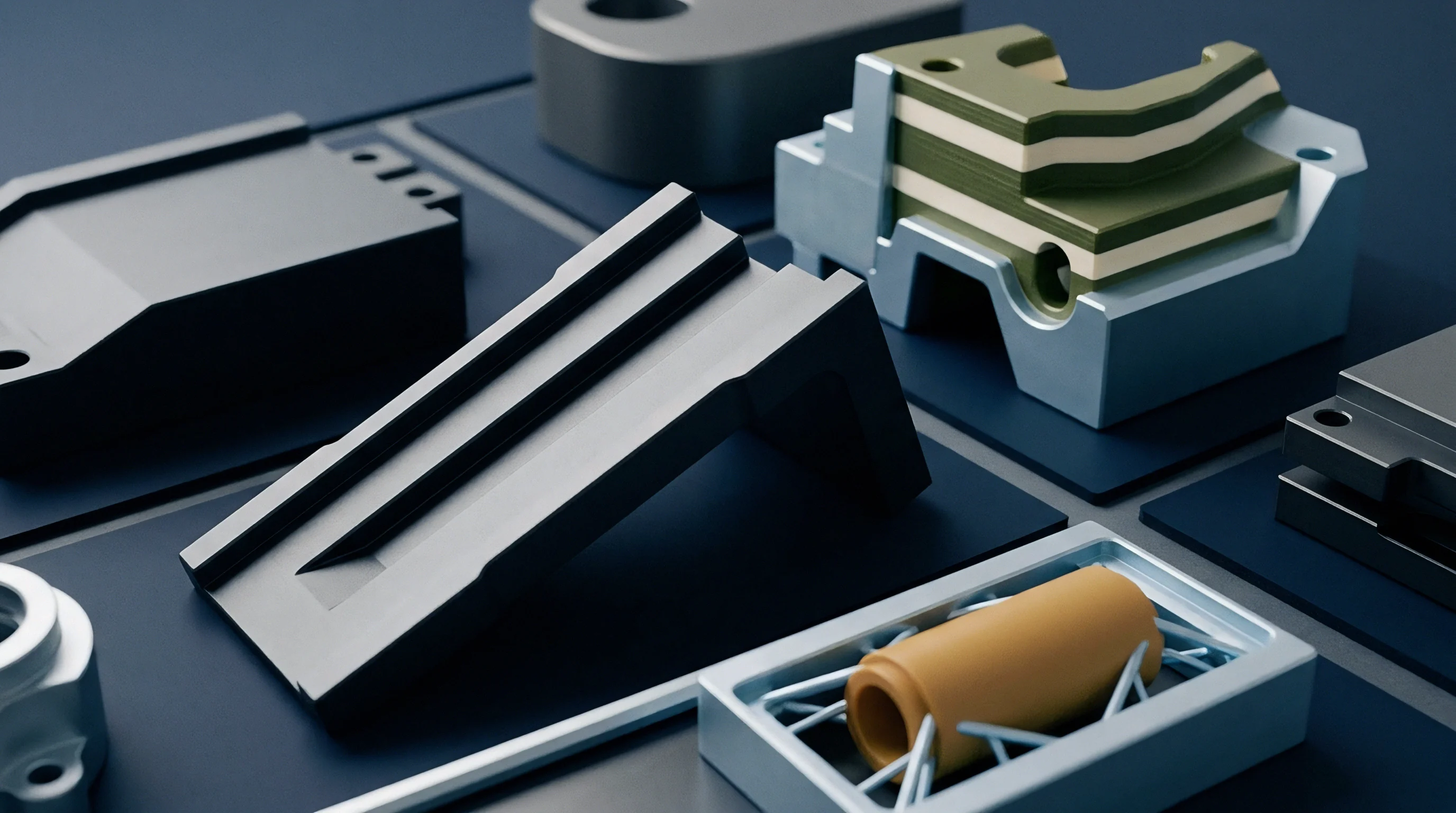
Numerical simulation of injection molding cooling stages requires coupled thermo-mechanical analysis to capture dynamic gap phenomena. Standard commercial fill and cool solvers assume constant thermal contact resistance at mold interfaces. This simplification yields inaccurate cycle time estimates for micro-structured inserts.
Advanced finite element programs solve structural deformation and thermal conduction equations simultaneously across every time increment.
Coupled Thermo Mechanical Numerical Modeling
Finite element routines update interfacial heat transfer coefficients based on calculated mechanical contact stresses at each nodal location. When structural solvers compute surface separation between the insert base and pocket floor, thermal subroutines automatically swap high metallic conductance values for low gas-gap conduction properties. Non-linear contact algorithms handle the transition between mechanical stick, slip, and full physical separation.
Computational convergence requires refined mesh density near the seating boundaries, with element edge lengths scaled below twenty micrometers.

Boundary Condition Parameterization for Finite Element Solvers
Accurate transient simulation relies on precise input parameterization for material hardness, surface roughness profiles, and pressure decay rates. Solvers apply dynamic user subroutines to adjust thermal conductance continuously throughout the simulated cycle time.
- Pressure Dependent Conductance Curves define the exact non-linear decrease in heat transfer capability as mechanical contact stress drops from peak injection levels down to zero.
- Gap Conductance Distance Tables provide explicit thermal conductivity inputs for air, vacuum, or venting gas mediums across separation distances ranging from 0.1 to 50 micrometers.
- Temperature Dependent Hardness Functions modify the metallic micro-hardness parameter within asperity deformation models during high-temperature Variotherm cycling.
- Transient Cavity Pressure Boundary Mapping imports real pressure sensor curves directly into structural solvers to drive accurate plate deflection relief calculations.
Under standard tooling procurement specifications under ISO 1101, simulation results used for mold design sign-off must incorporate non-linear gap conductance algorithms whenever micro-feature depth-to-width aspect ratios exceed three to one.
Provision
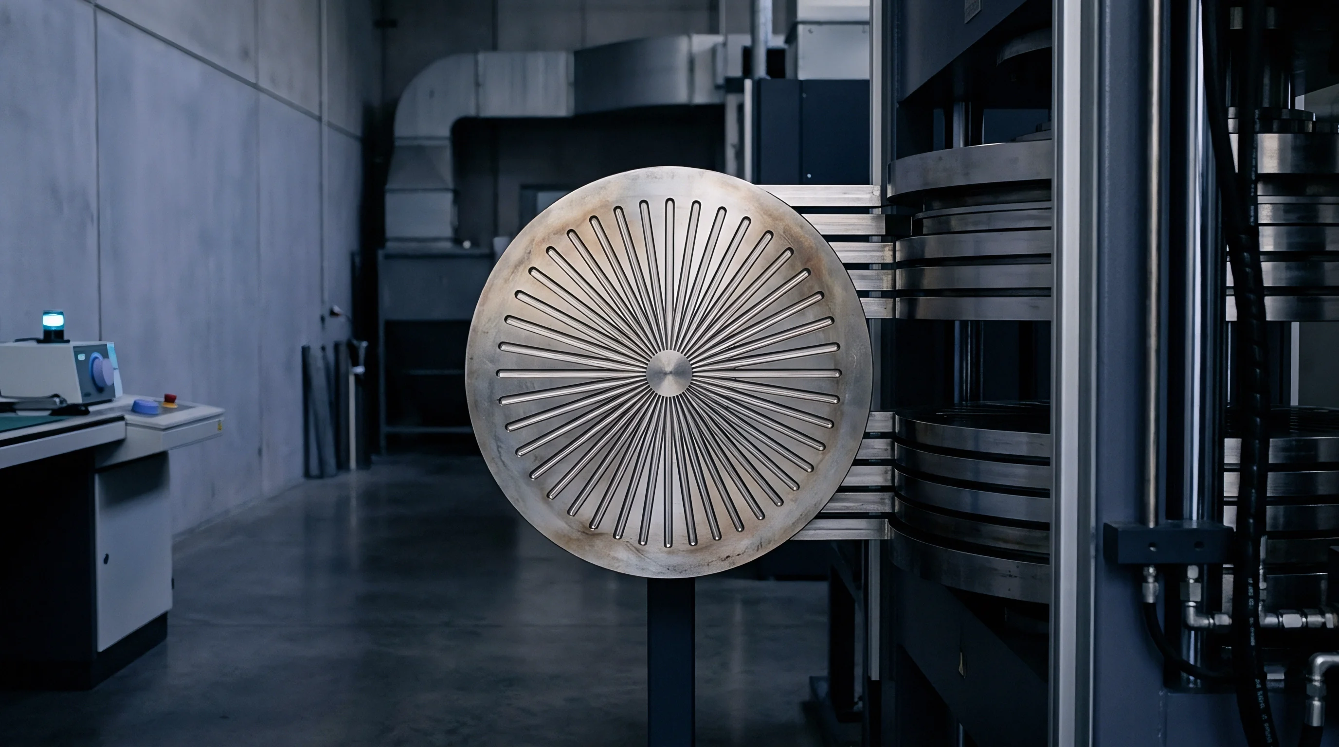
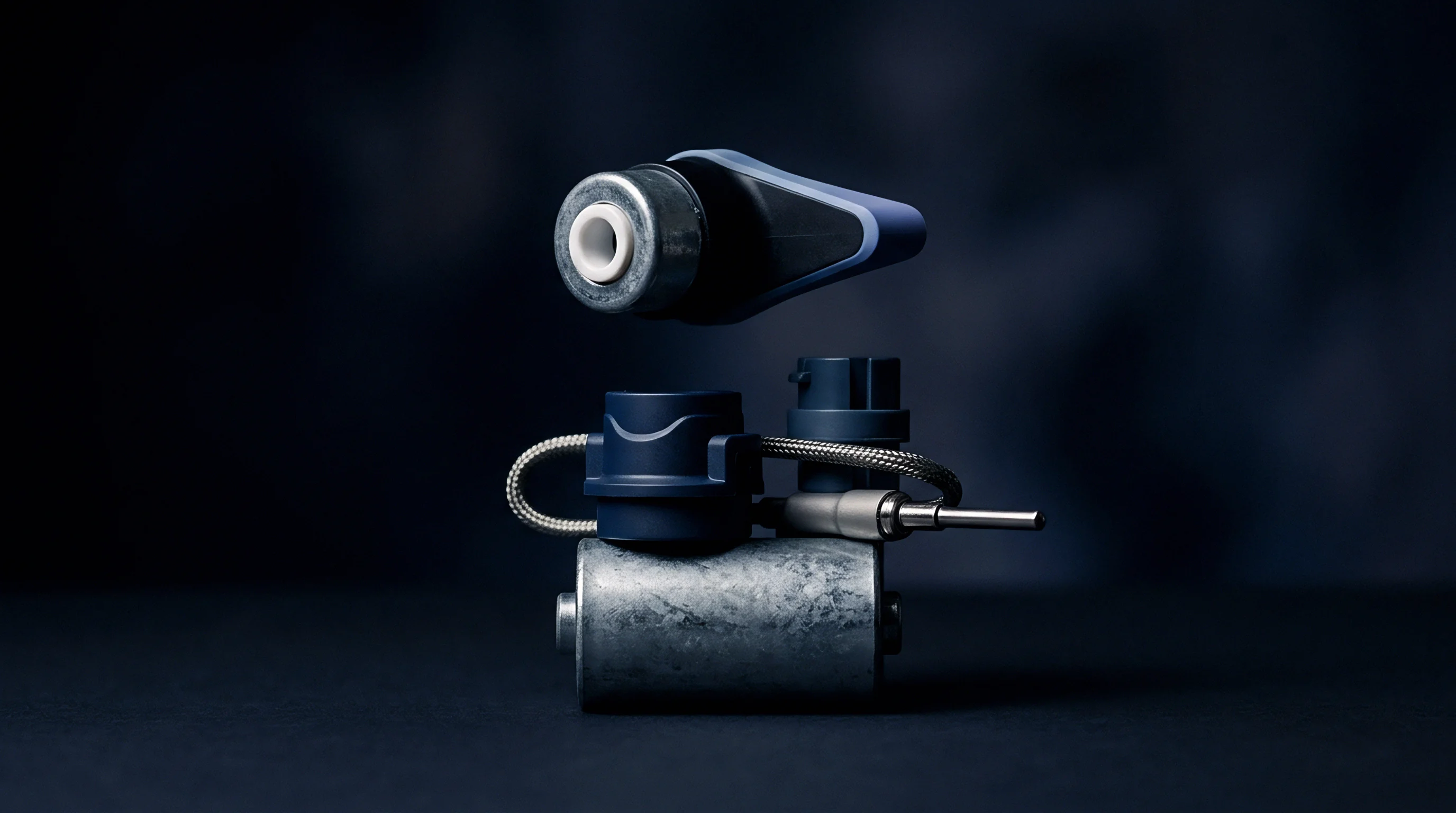
Mitigating transient thermal decoupling requires active mechanical engineering solutions within the mold architecture. Toolmakers implement active pre-load mechanisms, thermally conductive pastes, or vacuum-assisted seating systems to maintain interfacial contact throughout the entire molding cycle. Spring-loaded Belleville washer stacks placed behind the insert apply continuous mechanical pressure, suppressing gap formation when cavity pressure collapses.
Mechanical Strategies to Mitigate Interfacial Separation
Flexible mechanical mounts compensate for structural relaxation of the cavity plate. High-temperature thermal interface materials applied to the pocket floor bridge residual microscopic air gaps, elevating minimum baseline conductance to eight hundred Watts per meter Kelvin. Alternatively, direct-cooled inserts featuring integrated conformal cooling channels eliminate the pocket floor interface entirely.
Conformal channels printed directly within the insert metal extract heat without transferring energy across external contact boundaries.
| Tooling Architecture Selection | Initial Tooling Surcharge (EUR) | Cycle Time Impact (s) | Maintenance Cost / 100k Shots (EUR) | Thermal Decoupling Mitigation |
|---|---|---|---|---|
| Passive Pocket Standard Insert | 0 | + 4.2 | 150 | Uncontrolled (Severe Gap) |
| Spring Pre-Loaded Mechanical Insert | 2800 | + 1.1 | 450 | Partial (Controlled Gap) |
| Active Hydraulic Retention Inset | 7500 | – 0.8 | 1200 | Complete Elimination |
| Direct Conformal Cooled Laser Sintered Inset | 11200 | – 2.4 | 800 | Eliminated (No Interface) |

Financial Amortization of Active Thermal Tooling
Selecting advanced insert architectures alters capital expenditure and unit manufacturing costs. While passive inserts require minimal initial investment, longer cooling cycles and higher scrap rates increase per-part costs during mass production. Active retention systems increase upfront tool budget commitments but deliver predictable cycle times and superior micro-structure replication fidelity.
Investing in conformal-cooled micro inserts increases initial mold budgets by twenty-five percent while reducing unit production costs by fourteen percent over a two-million-shot tool life.
Tooling procurement contracts that allocate scrap cost liability to the mold maker force early design adoption of active insert retention systems. Tooling engineers specify dynamic thermal conductance verification checks during factory acceptance trials before signing off the final mold delivery documentation. Capital commitments remain secured when thermal performance meets specification targets under true volume production conditions.