Coherence Scanning Calibration Procedures for High Aspect Ratio Tool Steel Sidewalls
Calibrating optical coherence scanners on tool steel sidewalls requires specular tilt mapping, transfer function correction, and noise floor subtractive adjustment.
Calibrating optical coherence scanners on tool steel sidewalls requires specular tilt mapping, transfer function correction, and noise floor subtractive adjustment.
Optical slope limits require numerical aperture verification to prevent false zero-fill interpolation from corrupting areal texture calibration data.
Calibrated silicone replicas combined with optical profilometry yield sub-micron tool cavity topography metrics without destructive sectioning.
Selecting areal surface texture filter cutoffs under ISO 25178 matches transmission bandwidth to moulding replication limits, preventing false tooling rejects.
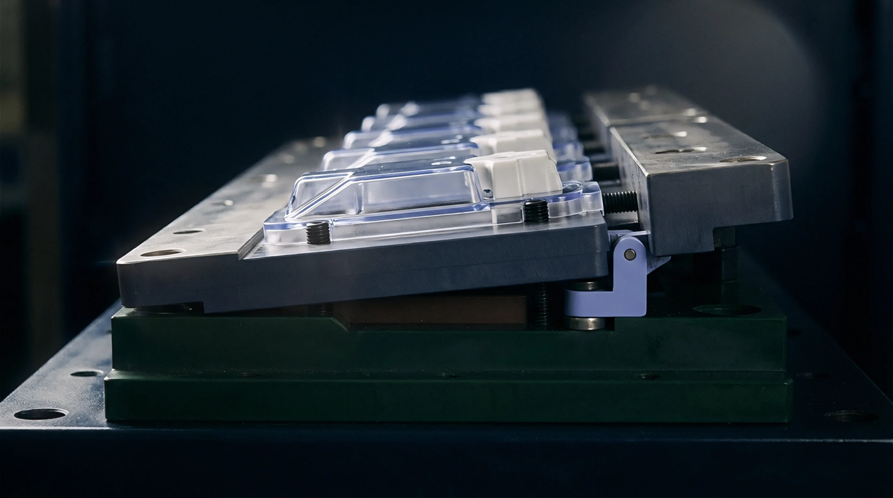
Optical profilometry non-destructively maps 3D tool cavity topography (Sa, Sz) to verify polished steel finishes and predict injection part ejection forces.
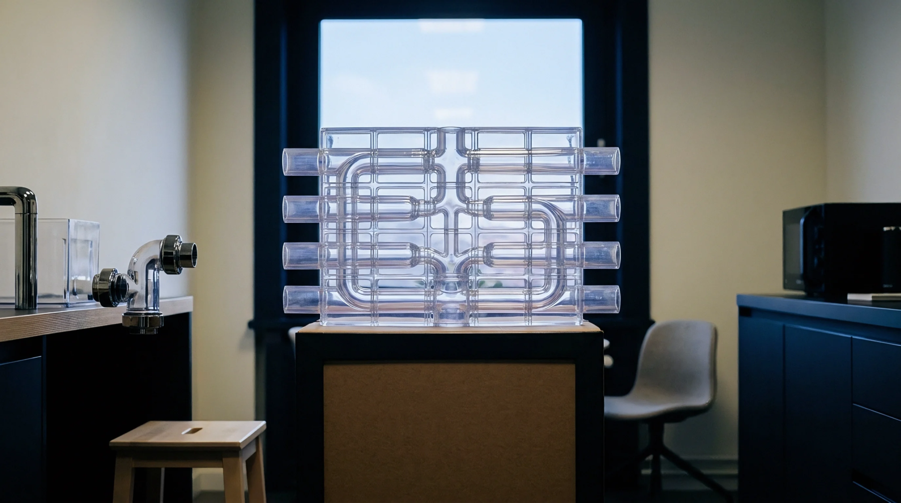
ISO 25178 defines 3D areal surface parameters like Sa and Sdr, replacing 2D profiles to qualify optical non-contact inspection on textured tool steel and mouldings.
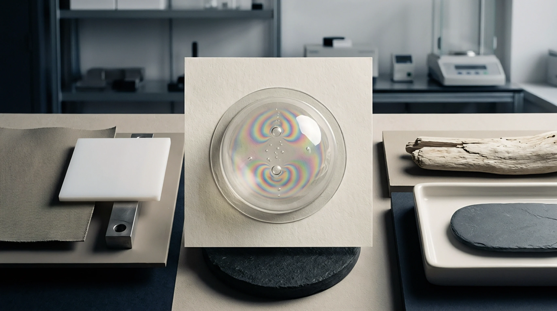
Verify hardened steel tool cavity topography using ISO 25178 areal parameters and filtered coherence scanning interferometry to guarantee polymer part release.
Expertise is a utility, not a secret. sentiention™ publishes its working knowledge as open reference: intelligence layer covering the materials it sources, the markets it enters, and the reference that serves both.