Injection Mould Cavity Surface Roughness Measurement Using Silicon Replicas
Indirect silicone replica metrology resolves deep mould cavity roughness parameters non-destructively within five percent variance of direct steel scans.

Cast
Measuring internal surface texture inside deep ribs, narrow cores, and spark-eroded blind holes in injection mould cavities presents clear physical challenges. Standard contact profilometers cannot extend into tight geometries without the probe assembly dragging against cavity walls. Direct optical metrology requires a straight line of sight, which breaks down inside internal undercuts, lifter pockets, or small valve gate wells.
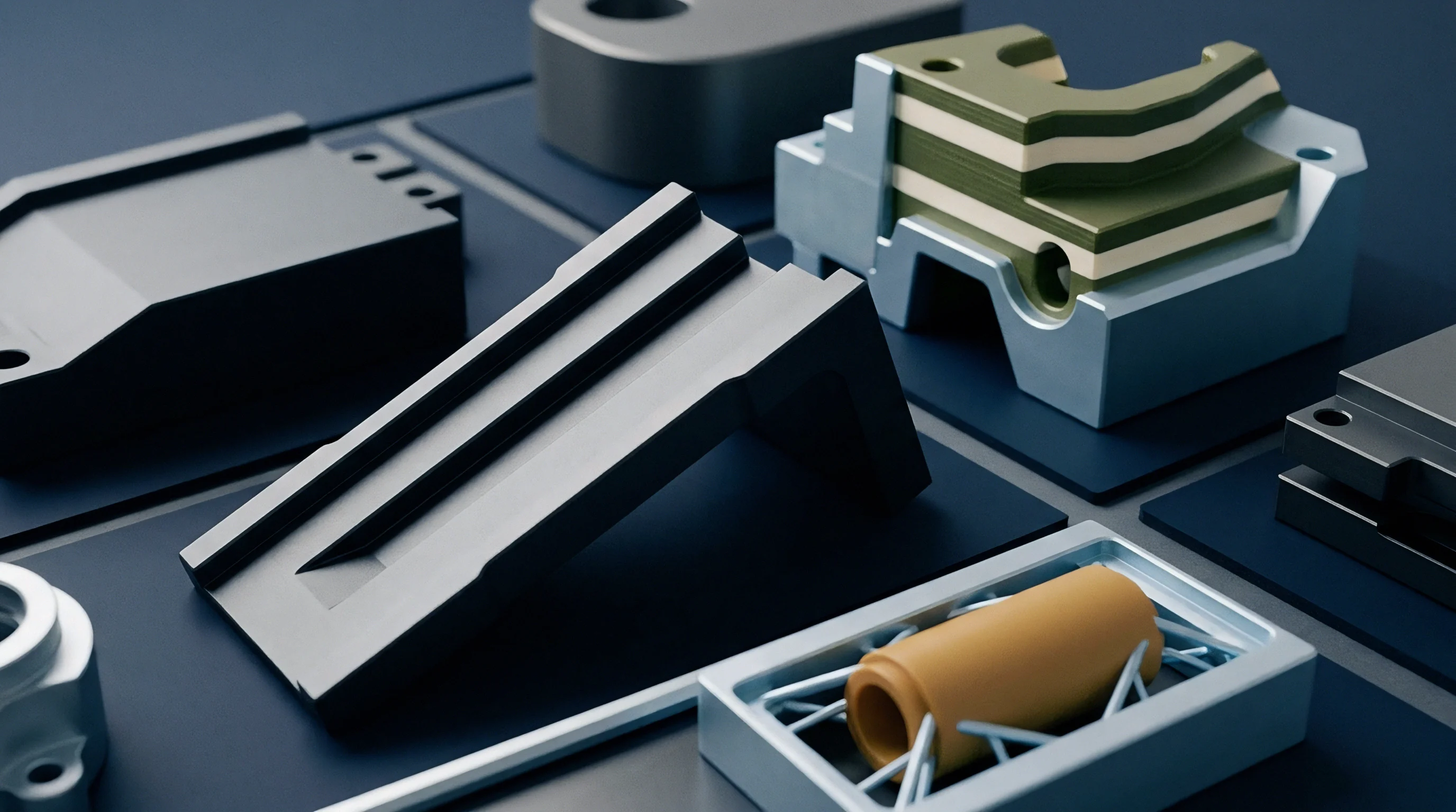
Polymer replication offers a practical indirect alternative, capturing three-dimensional micro-geometry without damaging tool steel or stripping down multi-plate mould bases.
Every microscopic mark created during machining remains captured on the steel surface.

Direct Profilometry Limits in Complex Mould Steel
Contact stylus profilometers rely on a diamond tip traversing a designated evaluation length, usually defined by ISO 21920 cutoff parameters. When a cavity feature presents a width under two millimetres or an aspect ratio exceeding five to one, physical contact instruments fail. The drive unit body collides with surrounding steel long before the stylus completes the required traverse length.
Direct optical systems, including coherence scanning interferometry and focus variation microscopy, encounter steep angle drop-offs on vertical cavity sidewalls. Light reflected from deep grooves scatters outside the objective lens collection cone, generating missing data points across steep surface gradients.
A soft elastomeric replica transfers high-frequency micro-roughness accurately only when the unmixed polymer viscosity allows complete capillary flow into surface peaks and valleys.
Indirect surface measurement solves accessibility limitations by converting a negative cavity void into an accessible positive impression. A liquid or paste polymer flows across the steel surface, fills microscopic tool marks, and cures into an elastic solid. Technicians remove the solid impression and place it under laboratory metrology instruments without spatial geometric constraints.
Surface roughness values measured on the flexible replica mirror the inverse topography of the cavity steel, provided the replication material exhibits zero physical tearing, low volumetric shrinkage, and high fidelity down to sub-micron scales.
Elastomeric Replication Mechanics
Topography transfer requires complete liquid wetting of the metal surface. High surface tension in the unmixed liquid resin causes air bridging across sharp microscopic valleys, resulting in artificial smoothing of the measured roughness profile. Low-viscosity siloxane polymers combined with proper surface cleaning allow complete fluid penetration into electro-discharge machining craters and polished tool surfaces alike.
| Cavity Feature Geometry | Contact Stylus Probe Constraint | Replica Impression Capability | Achievable Roughness Resolution |
|---|---|---|---|
Properly cleaning the steel ensures reliable adhesion without surface contamination.
Skipping surface texture verification on deep rib features leads to unexpected part ejection dragging, increased ejection forces, and costly tool rework during initial production bring-up.


Cure
Two-component siloxane polymers transition from a fluid state to an elastic solid through platinum-catalyzed addition polymerisation. Addition-cure polyvinylsiloxanes generate no volatile reaction side products during cross-linking, unlike older condensation-cure silicones that release ethanol and suffer linear shrinkage over time. Maintaining high dimensional stability during cross-linking ensures that microscopic peak-to-valley geometry remains uncompressed and undistorted across the evaluation area.
Polysiloxane compounds cure at room temperature without requiring external heat.
Polysiloxane Cross-Linking and Volumetric Stability
Volumetric shrinkage during polymer cross-linking introduces direct measurement error into indirect surface metrology. Addition-cure siloxanes yield linear shrinkage values below 0.1 percent when mixed at exact stoichiometric ratios. The cross-linking reaction proceeds at room temperature without exothermic heat spikes that could induce thermal contraction stress inside deep tool pockets.
The elastomer maintains constant volume across varied ambient toolroom temperatures, preserving spatial frequency relationships between fine scratch networks.
Curing two-part polyvinylsiloxanes at 21 degrees Celsius yields a linear volumetric shrinkage below 0.1 percent after twenty-four hours of cross-linking.
Viscosity selection governs initial surface wetting speed versus material slumping on vertical cavity faces. Ultra-low viscosity siloxanes flood fine micro-cratering effectively but run off vertical sidewalls before cross-linking completes. Thixotropic paste compounds remain stationary on vertical faces, though they demand higher manual application pressure to force fluid into deep micro-cracks created by spark erosion.
Entrained Gas Mitigation and Viscosity Control
Entrapped air bubbles severely distort surface profile accuracy.
Manual mixing introduces micro-bubbles into liquid siloxane compounds. During application, these entrapped air bubbles migrate toward the steel interface, forming hemispherical voids that metrology software registers as artificial surface peaks on the negative impression. Dispensing systems utilizing dynamic static-mixing nozzles eliminate atmospheric air entrainment during component blending.
- Incomplete polymer stoichiometry creates sticky surface films that tear during cavity extraction and leave material residue on tool steel.
- Micro-void nucleation from entrapped atmospheric air distorts optical focus variation systems by creating false geometric depressions.
- Excessive thermal shrinkage from uncalibrated exothermic reaction kinetics distorts spatial wavelength spacing across large evaluation lengths.
- Inhibited platinum catalysts resulting from contact with sulfur compounds or amine-cured epoxy cleaners delay solidification and soften replica surfaces.
Indirect replication protects delicate tool steel from mechanical damage during testing.
Minor surface cloudiness on the elastomeric impression often originates from solvent cleaning residue rather than incomplete polymer cross-linking.
Gauge
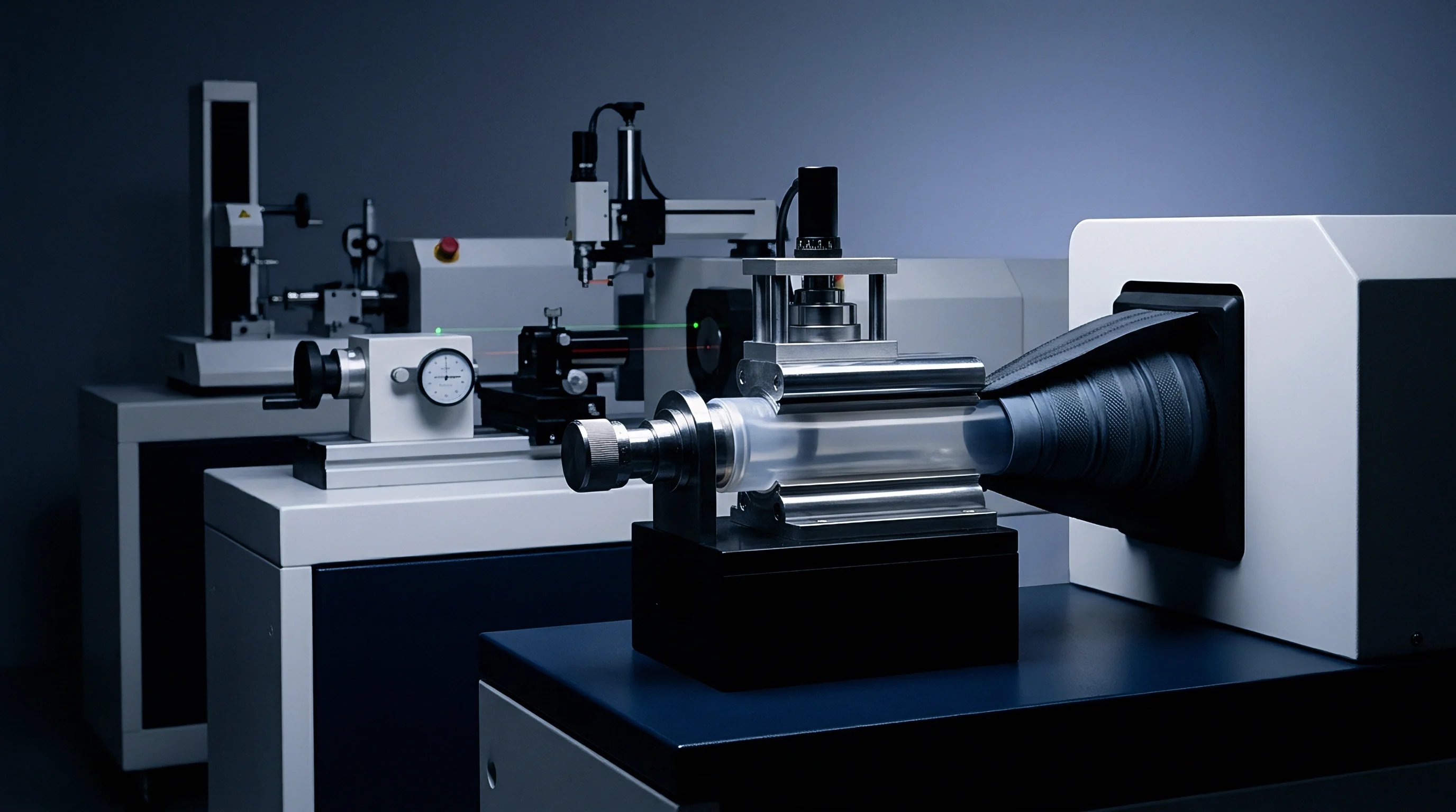
Surface topography measurement transfers from the physical toolroom to the metrology bench once the elastomeric negative solidifies. Metrologists choose between contact stylus instruments and non-contact optical profilometers to evaluate the elastomeric surface. Material compliance creates specific optical and mechanical challenges during inspection that differ significantly from direct steel measurement routines.

Optical versus Tactile Measurement on Flexible Substrates
Tactile stylus profiling applies a vertical contact force, typically between 0.75 millinewtons and 0.075 millinewtons, through a diamond tip with a radius of two or five micrometres. Steel surfaces withstand these loads without plastic or elastic deformation. Elastomeric replicas, exhibiting Shore A hardness values between 40 and 70, deform under stylus contact force.
The diamond point depresses surface peaks during the trace, causing artificial flattening of measured profile height parameters including Rp, Rz, and Ra.
Light easily penetrates transparent or unpigmented silicone matrices.
Non-contact optical methods eliminate mechanical indentation errors but introduce optical interaction anomalies. Focus variation and coherence scanning interferometry rely on light reflected directly from the surface interface. Pigmented, opaque silicone compounds reflect light cleanly at the outer boundary.
Semi-transparent or unpigmented silicones permit light penetration into the sub-surface material matrix, scattering photons internally and corrupting focal height determination.

Do Stylus Contact Forces Deform Soft Silicone Peaks during Scanning?
Mechanical stylus contact creates measurable elastic indentation on low-durometer silicones when peak radii are small. Applying a standard 0.75 millinewton stylus load to a 50 Shore A silicone replica deforms sharp surface peaks downward by as much as 0.35 micrometres. Reducing static stylus force to 0.075 millinewtons limits peak indentation within the noise floor of standard workshop instruments.
Modern metrology practice uses non-contact optical profilometry on opaque, highly filled silicones to avoid substrate compression entirely.
| Parameter | Steel Direct Measurement | Silicone Replica Measurement | Mean Variance | Transferred Cut-Off Filter |
|---|---|---|---|---|
Proper optical filtering removes high-frequency surface noise from datasets.
ISO 21920-3 mandates specific spatial cutoff filters based on target Ra values to prevent high-frequency noise from corrupting roughness profile evaluation.
Whether optical focus variation systems can reliably separate semi-transparent silicone surface light dispersion from true geometric roughness across sub-micron Ra ranges remains a point of active metrological debate.
Discrepancy
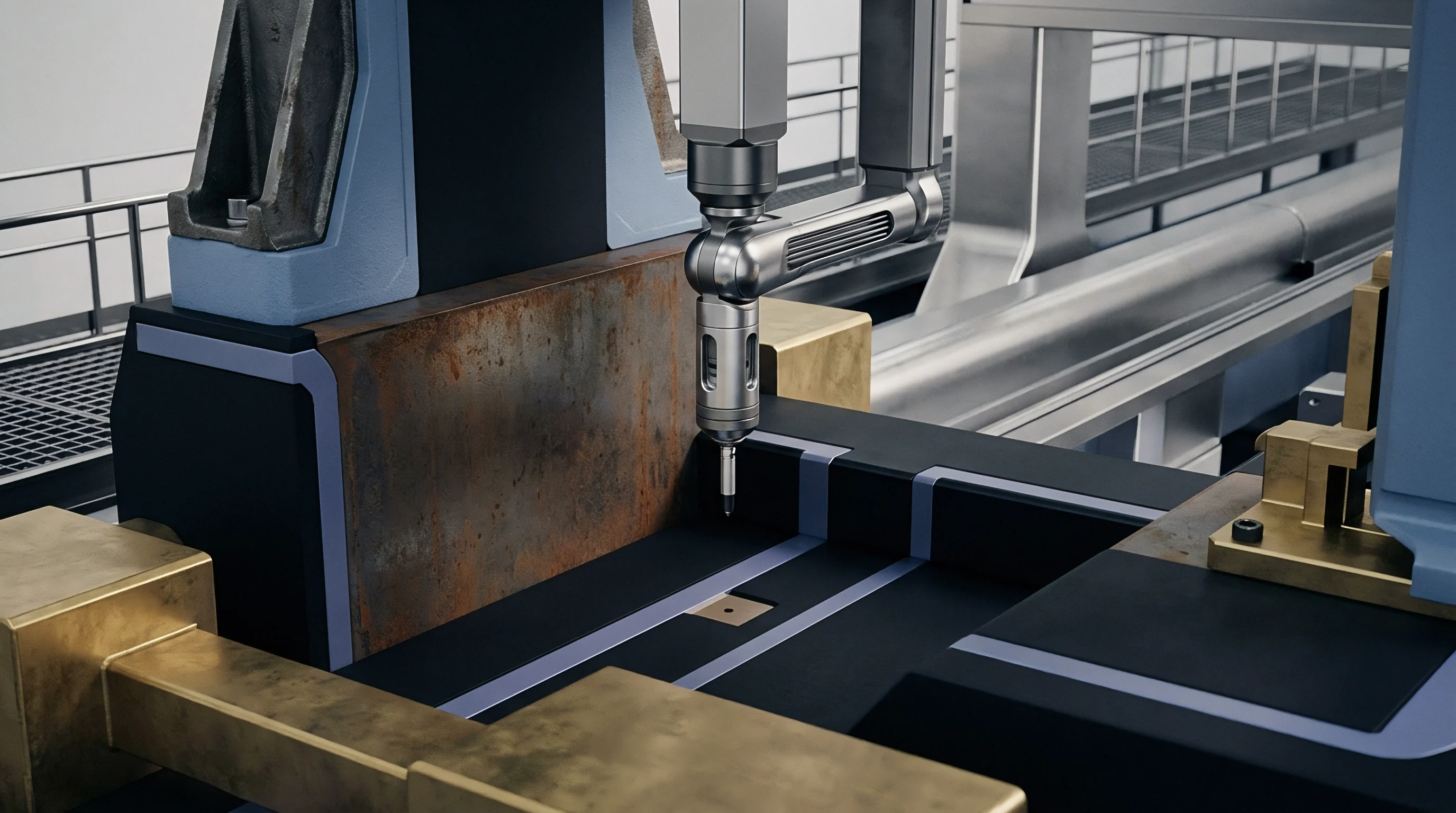
Systematic measurement offsets arise during indirect surface topography transfer due to polymer volumetric shrinkage and mechanical deformation during release. Quantifying these variances yields mathematical compensation factors that convert raw replica data into true cavity steel measurements. Calibration routines compare direct steel scans against replica scans across known reference specimens.
Polymer viscosity directly determines how deeply the resin wets the surface.

Calibration Curves and Transfer Loss Corrections
High-frequency spatial wavelengths experience attenuation during replication. Fine scratch marks with widths under one micrometre and depths under 0.2 micrometres may not fill completely with liquid resin, resulting in a low-pass filtering effect. Mechanical profiling of replicas systematically underreports maximum peak height Rp due to incomplete filling of sharp valley roots in the steel, which become sharp peaks on the elastomeric positive.
Consider an electrical discharge machined cavity with a targeted Ra of 1.60 micrometres. Direct stylus profiling on accessible flat areas establishes an accurate baseline. Replica scans using identical cutoff filtering yield a mean Ra of 1.52 micrometres, establishing a systematic transfer attenuation factor of 5 percent.
Metrologists apply a 1.05 correction multiplier to all subsequent indirect measurements taken from inaccessible zones within that specific cavity.
Tensile forces during extraction can temporarily strain and warp narrow surface features.
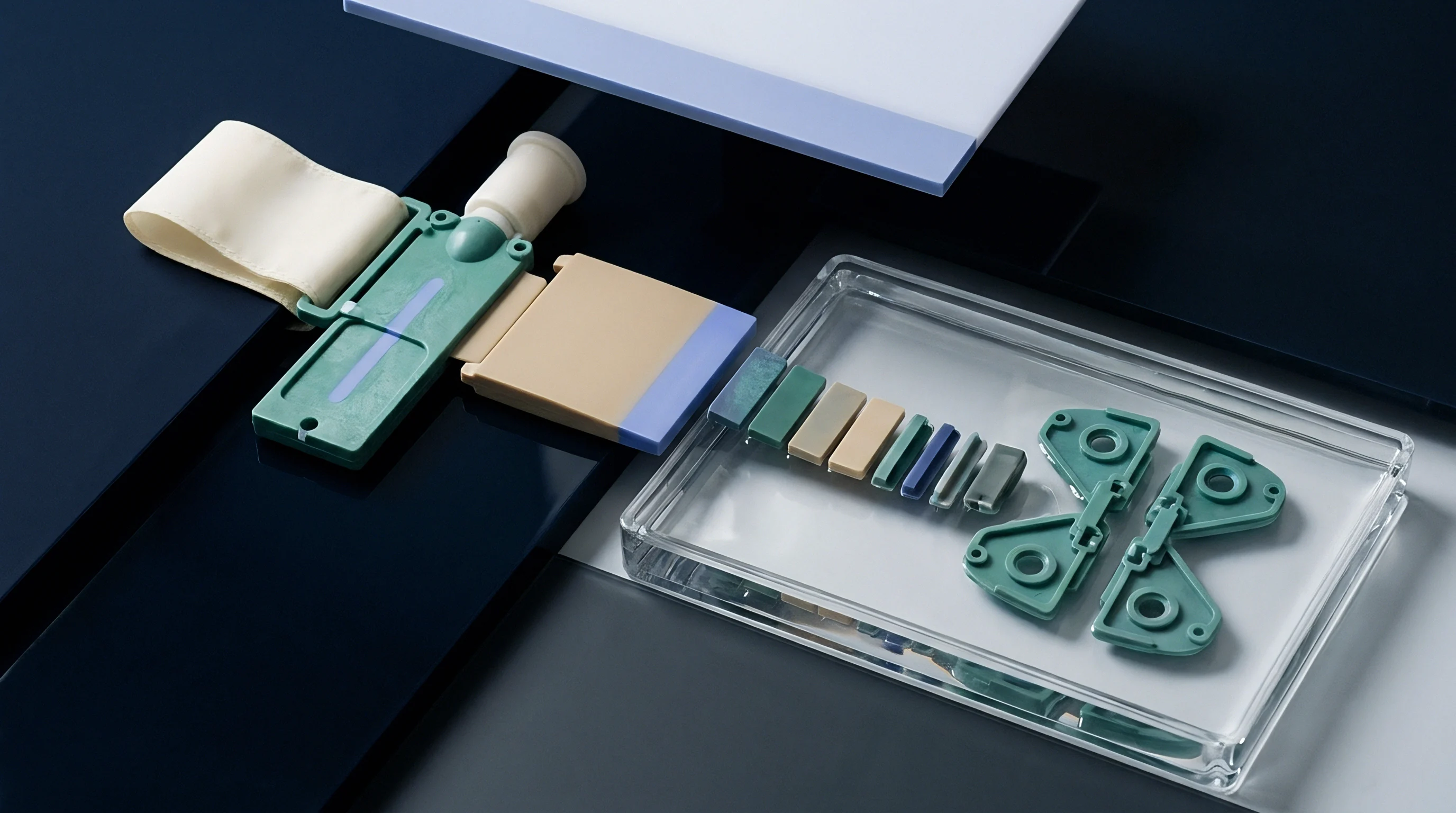
Undercut Retention and Elastic Recovery Strain
Extracting a solid impression from deep texture features or steep undercut angles subjects the cured polymer to transient tensile and shear strains. High-grade addition-cure silicones exhibit recovery rates above 99.8 percent after experiencing elongations up to 100 percent. If local extraction strain exceeds the elastic limit of the material, permanent deformation distorts the surface topography permanently.
- Degrease target mould steel using fast-evaporating solvent cleaner to remove protective oil films.
- Dry the cavity surface with compressed dry nitrogen gas to prevent solvent trapping beneath the polymer.
- Dispense dynamic two-component siloxane directly onto target steel using a fluid mixing tip held beneath the liquid pool surface.
- Allow full chemical cross-linking for fifteen minutes at room temperature without moving the mould plates.
- Peel the cured impression smoothly along the dominant draft vector to avoid excessive shear loading.
- Mount the cured impression on a rigid aluminum backing block using thin double-sided adhesive tape.
- Scan the replica using an optical profilometer with wavelength cutoff filters matched to expected surface roughness.
- Invert the measured profile z-height data in software to restore positive peak and negative valley orientations.
Deep narrow slots induce localized tensile strain during replica extraction that temporarily deforms micro-scale surface peaks.
Thicker replica backing layers dampen structural vibrations during stylus scanning while thin, unsupported impressions flex under mechanical contact.
Valuation
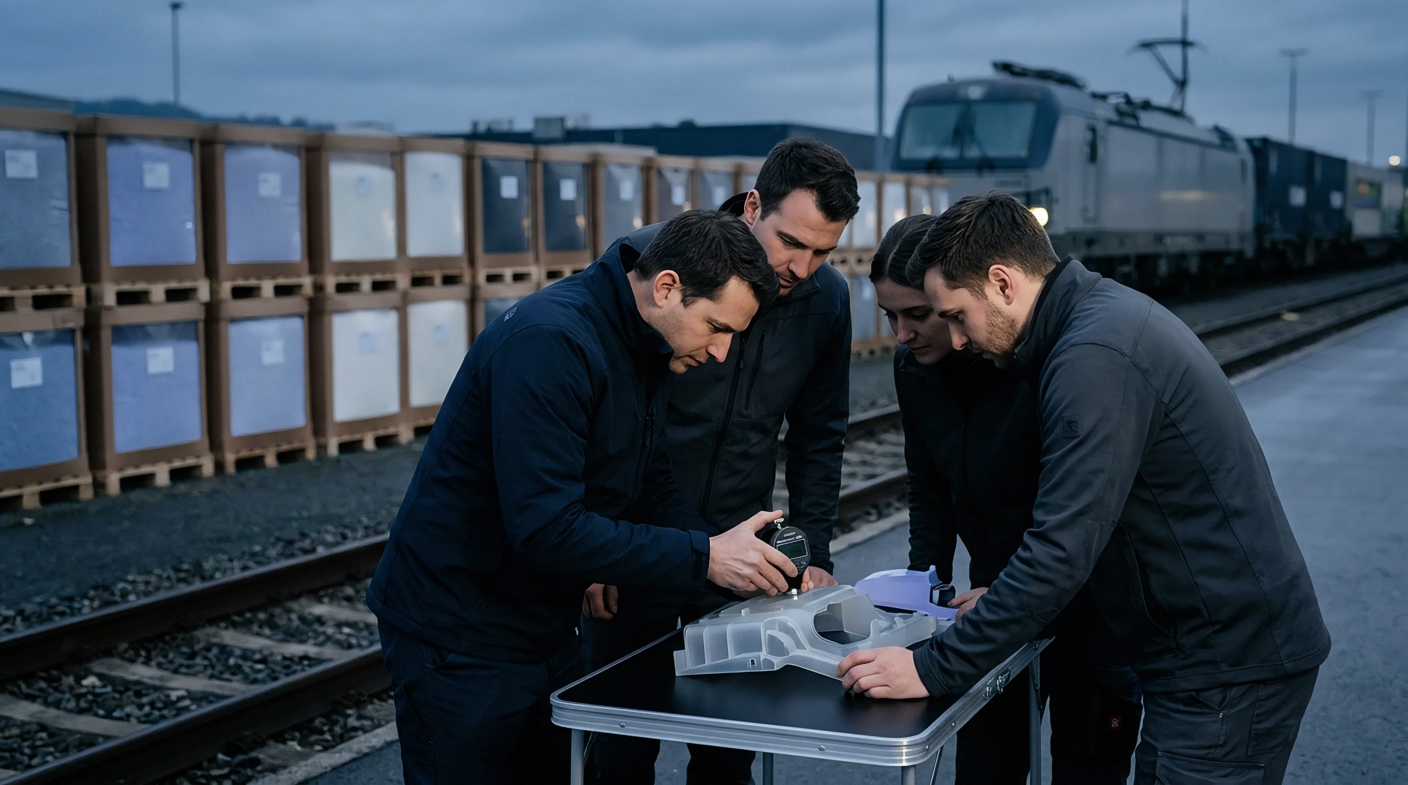
Tooling acceptance documentation relies heavily on verifiable surface finish metrics to validate cavity preparation prior to volume production. Surface roughness dictates moulding performance factors, including part release force, cosmetic gloss level, and secondary paint adhesion strength. Indirect replica metrology provides non-destructive proof of cavity finish compliance before a tool ships across international borders.
Surface roughness directly affects the force required to eject molded parts.
Tool Sign-Off and Surface Finish Compliance
Disputes over cavity texture specifications often center on discrepancies between physical visual standards like VDI 3400 or SPI finish scales and quantitative optical measurements. Visual comparison plates represent typical spark erosion or polishing appearances, but they do not account for localized tool wear or hand-polishing directionality. Integrating replica metrology into the tool sign-off dossier creates a permanent physical record of cavity topography at T1 sample approval.
- Verification protocol agreement establishes the exact replica material and optical filter settings before tool trials start.
- Dual-replica archiving secures both an initial sign-off cast and an intermediate wear benchmark for long production runs.
- Dispute resolution mapping defines direct cross-sectioning protocols when replica measurements fall within border uncertainty bands.
Taking regular replicas builds a historical record of tool wear over time.
Cavity Erosion Tracking across High-Volume Production
Abrasive glass-filled polymers, including PA66 with 30 percent glass fiber reinforcement, erode cavity steel at gate locations and convergence zones. As cavity roughness increases from continuous production wear, part ejection forces rise, extending overall cycle times. Taking periodic elastomeric replicas during scheduled maintenance shutdowns tracks micro-scale steel erosion without removing the mould base from the injection press.
| Finish Specification | Quality Defect Mode | Tool Modification Cost | Production Downtime Impact |
|---|---|---|---|
Draft angles significantly influence the stripping force during part ejection.
DIN 16742 Clause 5.2 specifies that cavity surface roughness deviations exceeding fifteen percent of the agreed baseline grant the buyer the right to withhold final tool release payments until optical replication confirms geometric compliance.